The method of removing the wallboard and hanging the roller is generally as follows:
1. Preparation before disassembly
In addition to the preparation of general mechanical parts for dismantling, they should also be equipped with removable (preferably equipped with rollers that can withstand high loads) gantry hangers, manual hoists and hooks with pulleys, support rollers and other parts sleepers, Wooden wedges, jacks, placement of support frames for machine wall panels (which can be welded by the length of the channel steel), and other items.
2 related accessories removal
Remove all the water and ink components from the roller.
Disconnect the iron bar connected to the host by the feeder, loosen the screw of the feeder and remove the feeder;
Remove the pedals on both sides of the machine; disconnect the air circuit and remove the front and rear air pumps;
Loosen the tension screw of the motor, remove the drive belt, loosen the motor ground screw, and remove the motor;
Use long ties to place the paper-receiving parts on both sides of the wall board at the delivery table to prevent the delivery part from tipping over due to changes in the local weight of the machine;
Loosen the hooks of the second color group and connect the ink components to the host. Raise them after shaking them out. Place them with suitable sleepers to cover the underside of the two side walls. Be careful not to touch the handles. Shaft gear
Disconnect the chain interface of the chain-feeding bite row. Before disconnecting, secure the rows of teeth on both sides of the interface to prevent them from falling freely. Then remove the entire chain from the delivery unit side by row and remove it.
Take apart the two pieces of pressing iron that the delivery part is connected with the host, cooperate with the gantry hanger, remove the delivery part, and place the board on both sides of the delivery table.
After releasing the lubricating oil in the fuel tanks on both sides of the main engine, remove all handles and long rods on both sides of the housing and remove the housing.
Loosen the four screws connecting the first color set ink inking unit and the mainboard wallboard, and lift the first color set ink transfer parts away. Place a suitable sleeper pad underneath the two side wallboards, and be careful not to damage them. Platen gear meshing pinion;
According to the principle of assembly and disassembly of general mechanical parts, the parts on the outer sides of the mainboard are to be removed in accordance with the ownership of the parts. Particular attention should be paid to the parts with the relative relationship between the parts with the transmission relationship, and they shall be placed in the storage tray after being removed.
3. Remove the roller sleeve (first remove one end)
Before disassembling the bushings, the drums must be properly cushioned, and at the same time, the delivery nip shaft, the delivery sprocket shaft and a long shaft between the two wallboards, etc. shall be prepared. The prepared sleepers and jacks shall be used to provide each zero. Parts pads are good, keeping their relative positions fixed, including the up and down, left and right positions must not have the slightest change, in order to prevent the sleepers from being compressed and deformed and the hard and hard contact between the jack head and the drum body and other defects, can be used wooden wedge into the gap, Tighten the matted object. This work must be careful. Then each roller sleeve can be taken out separately. If each roller pad is in good condition, the shaft sleeve should be taken out easily. In the process of picking up, it should be tried slowly, constantly checking the pad condition to prevent the shaft from jamming and the axis of the roller. Deflection caused damage to other parts and other accidents. After the shaft sleeves are removed one by one, the rollers and other rods to be clamped should remain stationary.
4. Remove the screws and pins
Loosen the large screws connecting the wall plate and the base, and use the nut cover tool to remove the pins that hit the base from the slope of the wall plate.
5. Open one side wall plate
The prefabricated wallboard support frame welded with channel steel is placed on the side of the base of the machine. It should be at the same height as the base block, with a length that is slightly longer than the length of the wall plate, and the support frame should be fixed to the base (welding can be used). Live), to prevent it from moving when moving the wallboard, hang the gantry hanger main beam on a manual hoist with a pulley hook, and push it into the middle of the machine.
After the wire rope is passed through the gourd, the wall plate is clamped firmly so that the upward pulling force point of the hoist is as far as possible in the midline of the wall plate, and the plane of the hoist should be ahead of the plane where the wall plate is located, so that the wire rope has an inclination angle to the moving direction of the wall plate.
Take off the screws that connect the wall plate and the base, tighten the wire rope, but do not tighten it so as not to lift the wall plate. Use square wood to hit the inside of the wall plate so that the wall plate moves outwards. At least three strike points must be used at the same time. In particular, the sleeves used for the swinging feed shaft and the delivery sprocket shaft and the wall plate hole are not removed in advance. The force is greater here and there should be a strike point in the vicinity.
Repeatedly tightening the steel rope and striking the wallboard outwards, the wallboard will be directed to the horizontal direction of the diagonal cable. Under the combined action of the horizontal force of the square wood, the slow outward parallel movement will gradually fall. On the support frame, the vertical component of the diagonal cable can guarantee that the wall plate will not overturn and stably shift.
In order to make the movement, the bottom surface of the wallboard and the plane of the support frame will not be damaged due to too much friction, some butter may be applied to the plane of the support frame in advance.
After the wallboard completely leaves the base and falls on the base, it can be slightly increased by using a manual hoist, and it is lifted by a gantry hanger. Note that the lifting weight of the manual hoist should be much larger than the weight of the wallboard. Fixed to prevent overturning.
6. Lift out the drum
After the side wall board is removed and removed, the work of lifting out the drum can be carried out. The hanging drum should be lifted from the top to the bottom. The lifting method of each drum is roughly the same, and the gantry hanger is pushed back to the middle of the machine. The rope into the "person" shape respectively hoisted the journal of the two ends of the drum, tighten the steel rope to make the drum axis as horizontal as possible, after the stable, the other end of the drum shaft sleeve removed, along the axis of the drum to push the gantry hanger, the drum shaft head Move away from the hole in the wall plate to raise the roller slightly and push the gantry to lift it out.
When the drum is placed, it should try to use the "v" type frame to support the journals at both ends of the drum. After all the drums are lifted off, the remaining wall panels should be properly protected against falling. The sprocket shaft and other structures of the long axis should be properly removed in principle to prevent deformation and bending.
Para cord
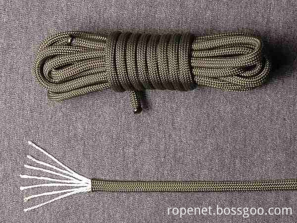
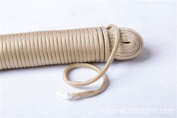
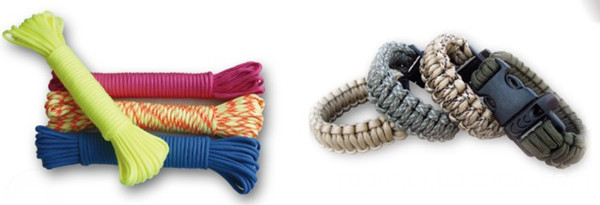
Military spec 550 cords constructed of 100% nylon with 7 strand high strength core covered by a polyester smooth jacket yielding a minimum tensile strength of 550 pounds. Braided sheath has a high number of interwoven strands for its size, giving it a relatively smooth texture. It is available in assorted colors and all have white core strands. These smaller cords can be used in a wide range of applications from tie-down straps to braided bracelets and any other non-life-safety applications.
Feature:
• Soft-hand feel
• Good stretch and versatility
•Seven strand Hi - tensile cord is rated at 550 lb
• Ideal rope for outdoor utility applications
Description of Para cord
1. Name: Para cord 550 Parachute Cord Lanyard Rope
2. Material: PP (Polypropylene), Polyester, Nylon
3. Over 100 colors for your choice.
4. Length: 50ft, 100 feet is standard packing.
5. Most popular: 4mm, 7 inner strands, 3 ply twisted line, strength 550LBS
6. Packing: Coil, Hank, Bundle, Reel, Shell Color Bag
7. Diameter Range: 2mm-32mm
8. Structure: 8-Strand, 16-Strand, 24-Strand, 32-Strand, 48-Stran


If you have any questions, pls send email to us directly.
Para Cord,Paracord Rope,Rope Bracelet,Parachute Rope
ROPENET GROUP CO.,LTD , https://www.cordnet.com